Exploring Gateware Design with Libero#
In this demonstration, we’ll be exploring the BeagleV-Fire gateware in the Libero Design Suite, making changes to the default gateware. This demo will serve as an introduction to the design tool, an alternative method for developing gateware.
Prerequisites#
The prerequisites required for creating the Libero project locally are:
Microchip design tools: Refer to the document here for installation instructions of microchip FPGA tools.
Python requirements for gateware build scripts:
pip3 install gitpython
pip3 install pyyaml
Build requirements:
sudo apt install device-tree-compiler
Tip
For convience, you can install a python command alias like so:
sudo apt install python-is-python3
This is optional, but remember to use python3 in later command examples if you don’t.
- Environment variables: The following environment variables are required for compilation:
SC_INSTALL_DIRFPGENPROGLIBERO_INSTALL_DIRLM_LICENSE_FILE
A script is provided for setting up these variables in the fpga tools installation section.An example script for setting up the environment is available here.
5. It is highly recommended to go through the Customize BeagleV-Fire Cape Gateware Using Verilog tutorial to understand the basics of the gateware structure.
Cloning and Building the Gateware#
First, we must source the environment to include the microchip tools.
source /path/to/microchip/fpga/tools/setup-microchip-tools.sh
Next, we’ll clone the gateware repository to get a local copy of the project.
git clone https://openbeagle.org/beaglev-fire/gateware.git
cd gateware
build-bitstream.py script to generate a Libero project for us,Important
python build-bitstream.py ./build-options/default.yaml # exploring the default gateware
This should start a big log stating the compilation of the project. First, the device tree overlays are compiled, which contain information for linux about the gateware.
Next, the Hart Software Services (HSS) is compiled. This acts as a zero-stage bootloader, configuring the Polarfire SoC and allowing services like loading the next stage bootloader and flashing the eMMC of the board.
Then the libero project generating is started. Here, TCL scripts inside the sources directory are
executed, starting with the BUILD_BVF_GATEWARE.tcl script. This stitches each HDL module, IP,
hardware configuration together in the gateware.
libero &
or from the start menu in Windows, and open the project file by pressing
CTRL+O and selecting the generated project as gateware/work/libero/BVF_GATEWARE_025T.prjx .
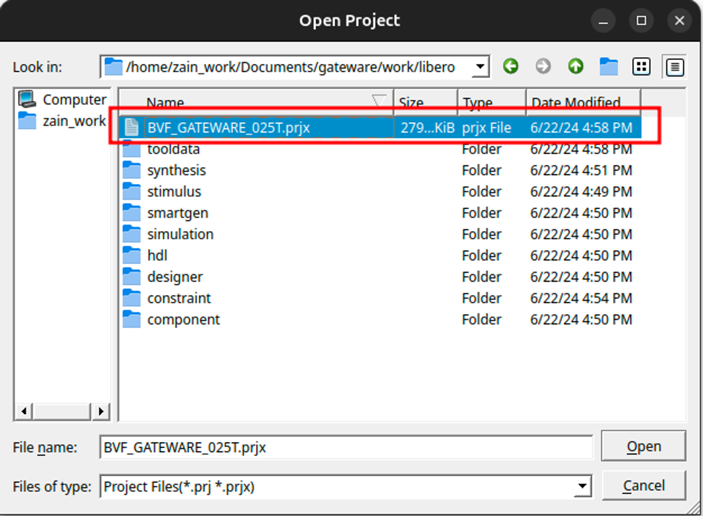
Fig. 467 Libero project location#
Exploring The Design#
Let the IDE load everything, and then you’re all set to browse around! You can go to the
Design Hierarchy view to look at all Smart Design components. Here, all the gateware components
are listed in block-like views. Double click the DEFAULT_****** option in the hierarchy to have a look
at the whole gateware. You should also be able to see the cape, M.2 interface and the RISC-V subsystem
modules. These modules are explained in Gateware Introduction.
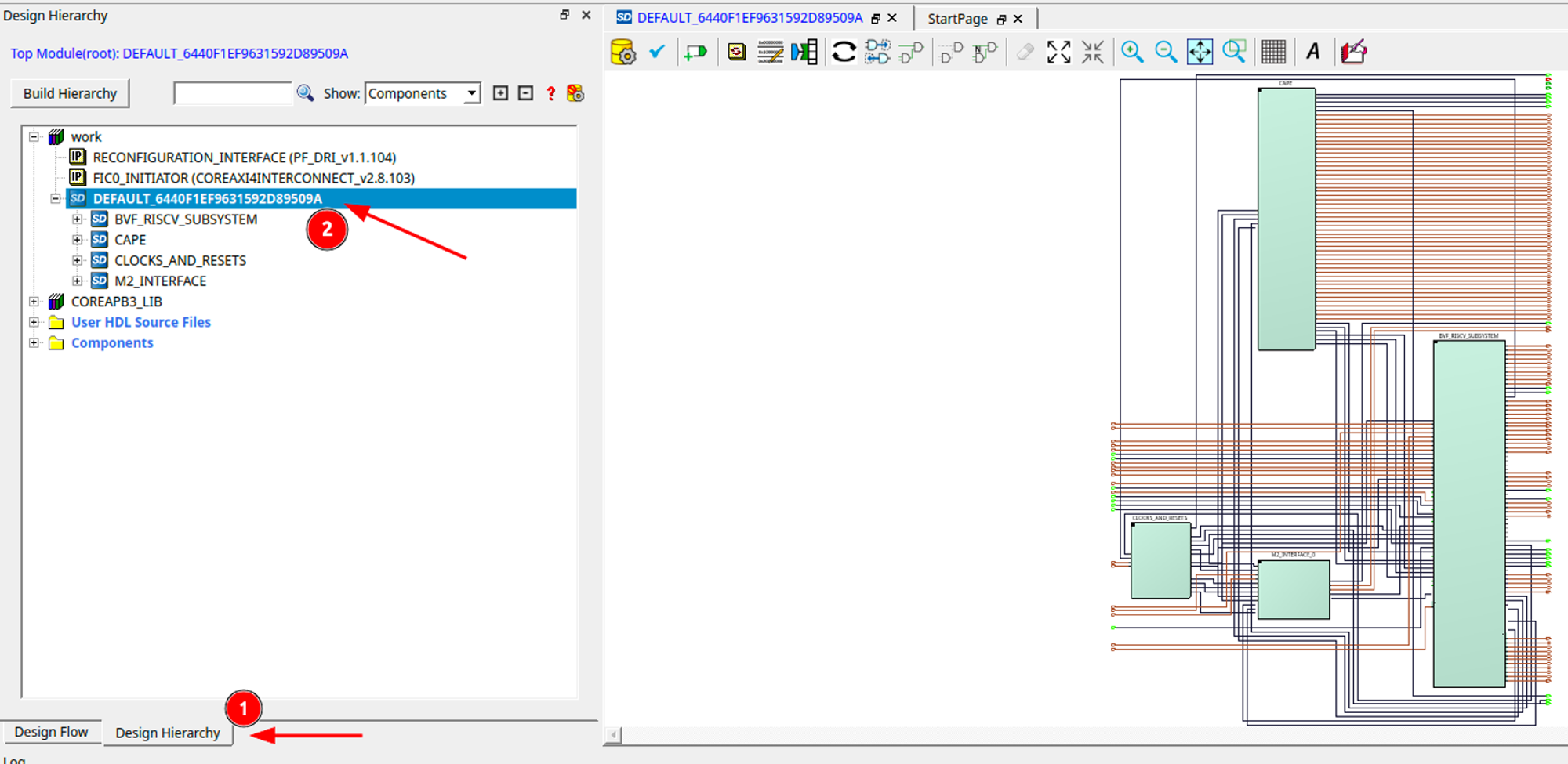
Fig. 468 Libero gateware overview#
Adding Custom HDL#
blinky.User HDL Source Files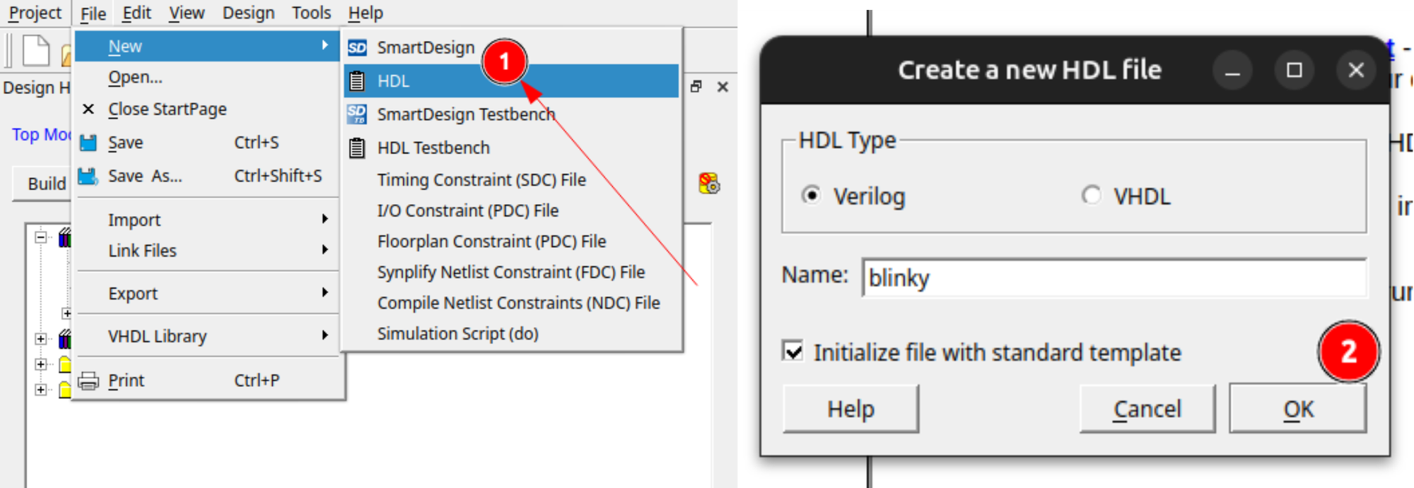
Fig. 469 Adding new HDL#
Next, add this code to the file:
`timescale 1ns/100ps
module blinky(
input    clk,
input    resetn,
input [27:0] gpio_out,
input [27:0] gpio_enable,
output [27:0] modified_gpio,
output [27:0] modified_gpio_enable
);

reg [22:0] counter;
assign modified_gpio = {gpio_out[27:6], counter[22], gpio_out[4:0]};
assign modified_gpio_enable = {gpio_enable[27:6], 1'b1, gpio_enable[4:0]};

always@(posedge clk or negedge resetn)
begin
    if(~resetn)
        begin
            counter <= 23'h0;
        end
    else
        begin
            counter <= counter + 23'b1;
        end
end
endmodule
Build Hierarchy button in the Design Hierarchy window to refresh it,No on the dialog that follows since we’ve described the ports completely in our HDL.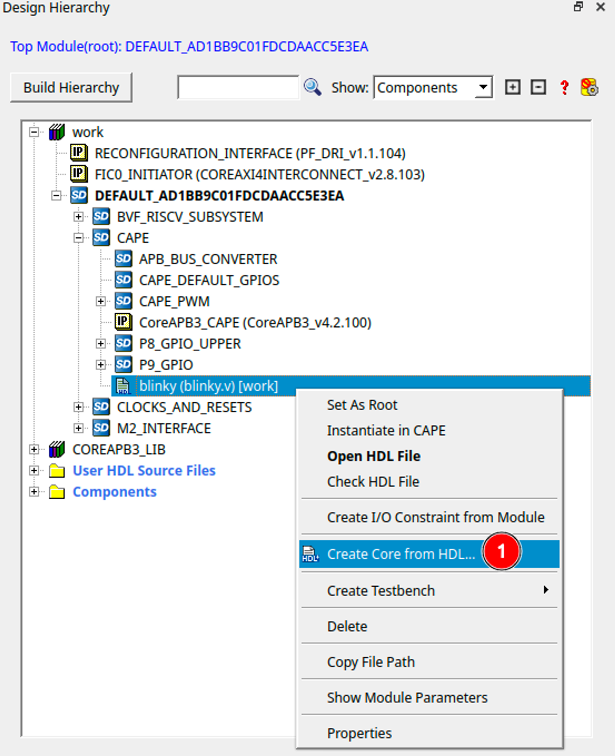
Fig. 470 Create core from HDL#
CAPE design under the DEFAULT_**** smart design,blinky file appearing in the work section into the cape design.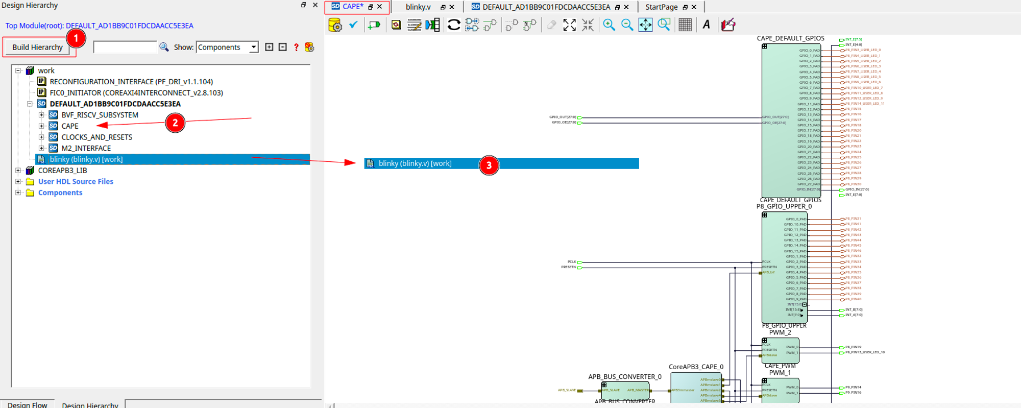
Fig. 471 Add blinky to cape#
Making The Connections#
GPIO_OUT and GPIO_OE to the CAPE_DEFAULT_GPIOS module.GPIO_OUT and the GPIO_OE terminals of the capegpio_out and the gpio_enable pins respectively.CAPE_DEFAULT_GPIOS module.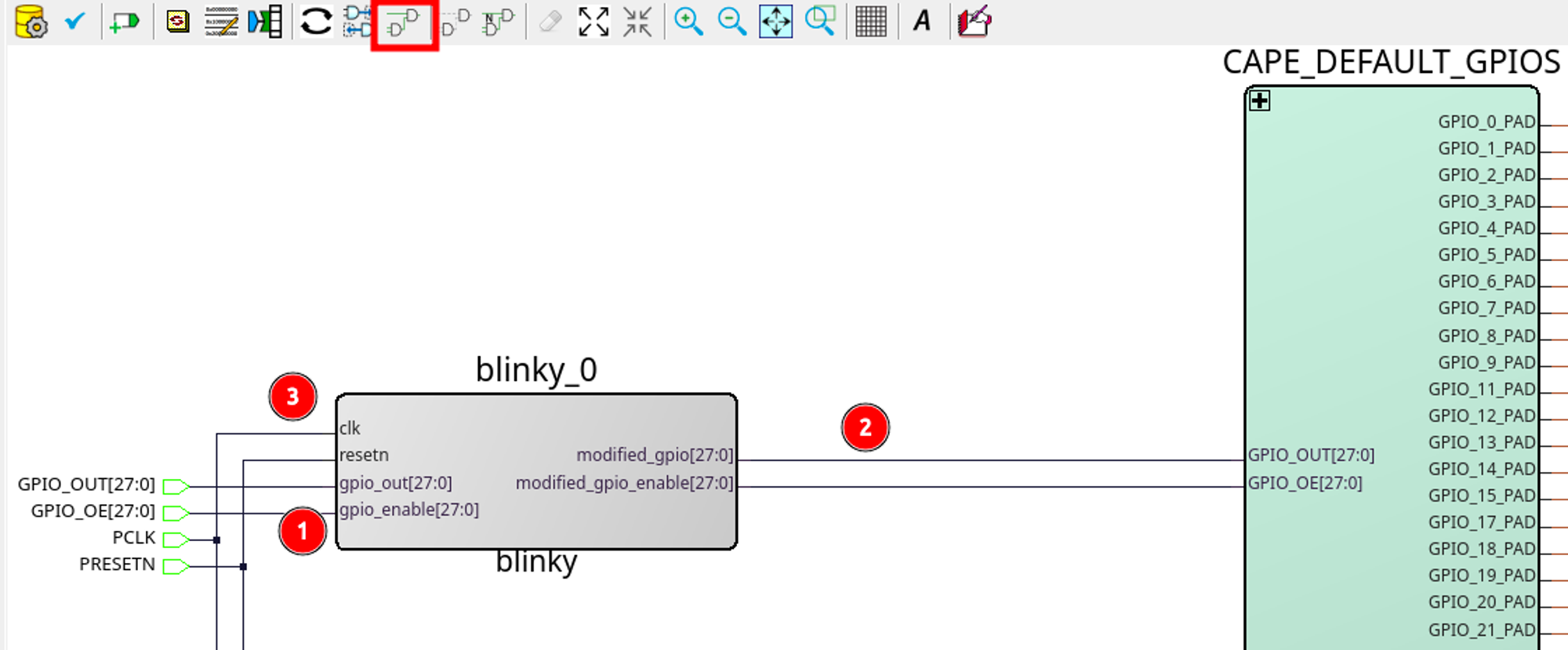
Fig. 472 Connect blinky to cape#
PCLK and the PRESETN pins below in the cape.Exporting The Design#
Exporting the Cape#
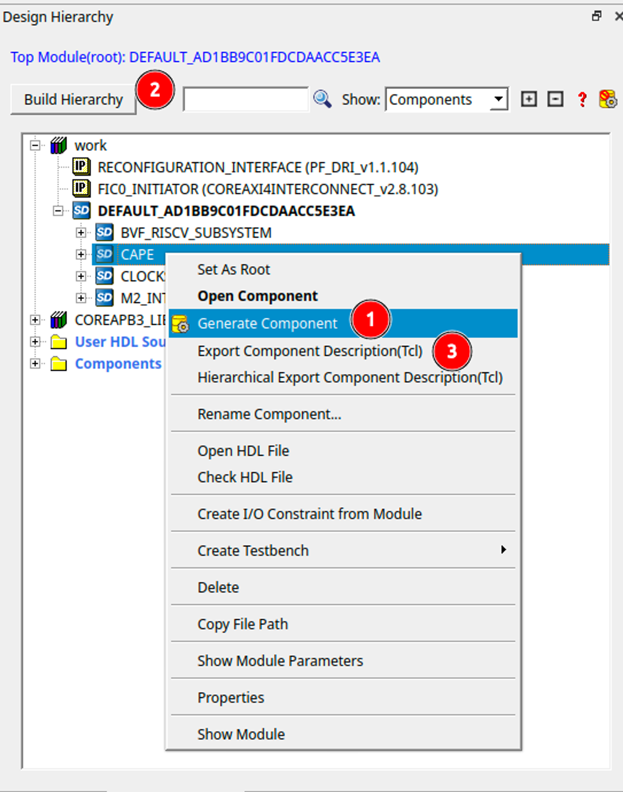
Fig. 473 Regenerate designs#
Now, simply copy it into the gateware at the following path.
cp ~/export/gateware/CAPE.tcl ~/gateware/sources/FPGA-design/script_support/components/CAPE/DEFAULT/
Exporting The HDL#
mkdir ~/gateware/sources/FPGA-design/script_support/HDL/BLINKY
cp ~/gateware/work/libero/hdl/blinky.v ~/gateware/sources/FPGA-design/script_support/HDL/BLINKY/
Export Component Description.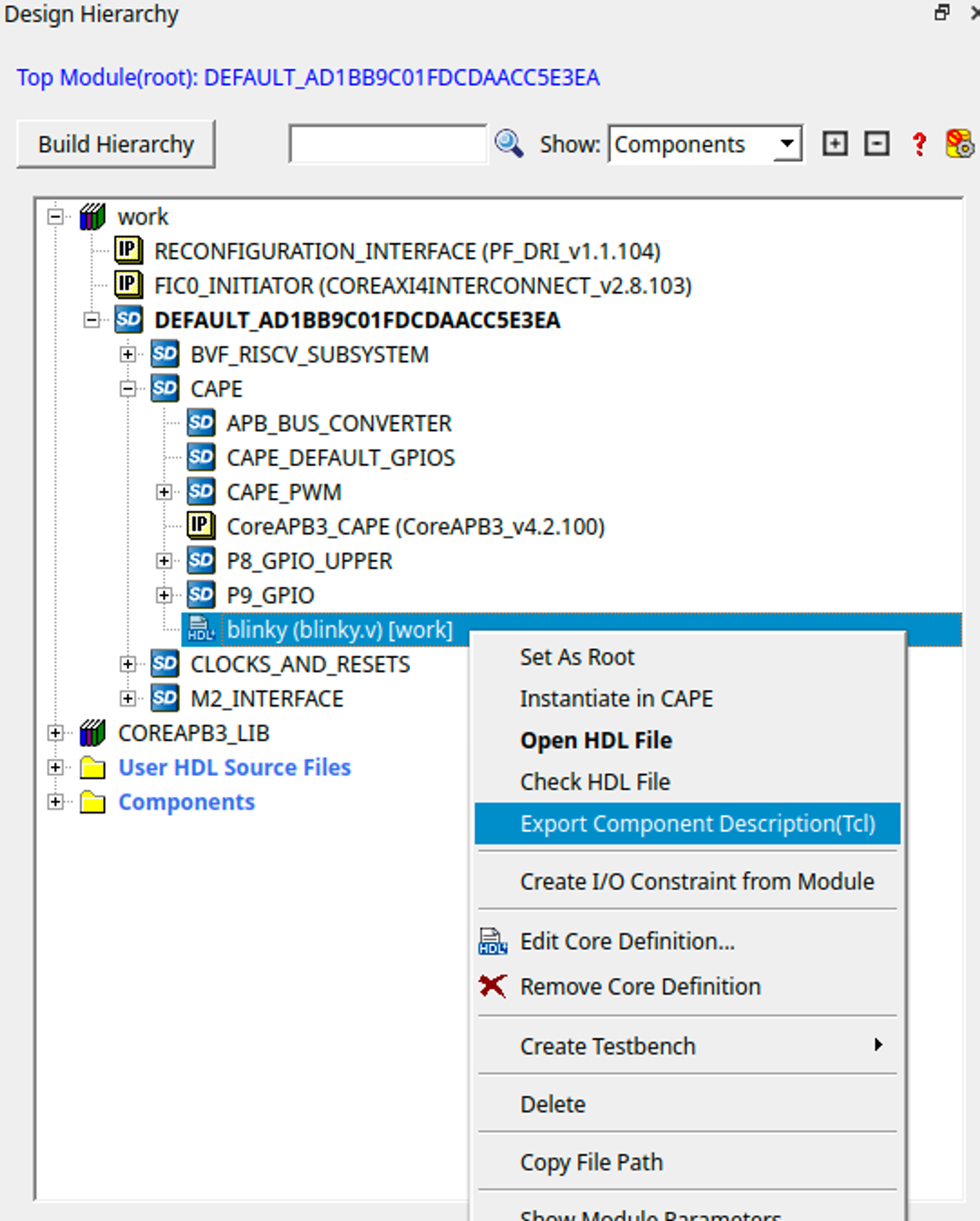
Fig. 474 Export HDL#
Now, concatenate the contents of this exported file to our gateware’s HDL sourcing script at gateware/sources/FPGA-design/script_support/hdl_source.tcl like so:
cat blinky.tcl >> ~/gateware/sources/FPGA-design/script_support/hdl_source.tcl
-file argument in the line with -file $project_dir/hdl/blinky.v. -hdl_source {script_support/HDL/AXI4_address_shim/AXI4_address_shim.v} \
-hdl_source {script_support/HDL/BLINKY/blinky.v} # ⓵ Source the script below line 11
#......
#...... towards the end of the file
hdl_core_assign_bif_signal -hdl_core_name {AXI_ADDRESS_SHIM} -bif_name {AXI4_INITIATOR} -bif_signal_name {RREADY} -core_signal_name {INITIATOR_OUT_RREADY}
create_hdl_core -file $project_dir/hdl/blinky.v -module {blinky} -library {work} -package {}
# ⓶ Add the core at the end of the file
Feel free to cut any extra comment lines introduced when concatenating above. Verify your script as above, save it and now you’re good to compile your project!
Important
build-bitstream.py will fail to properly checkout the required licenses.Now is a good time to check in your changes to git:
cd ~/gateware
git add ./sources/FPGA-design/script_support/components/CAPE/DEFAULT/CAPE.tcl
git add ./sources/FPGA-design/script_support/hdl_source.tcl
git add ./sources/FPGA-design/script_support/HDL/BLINKY/blinky.v
git clean -df
Final Verification#
Go ahead and run the python script to build the gateware and verify your changes:
python build-bitstream.py ./build-options/default.yaml
The Execute Script command succeeded.
The BVF_GATEWARE_025T project was closed.
change_gateware.sh script.Tip
For a more direct route you can copy the generated bitstream straight to your Beagle and try the result immidiately:
scp -r ./bitstream beagle@<ip or name here>:
On the beagle, use:
sudo /usr/share/beagleboard/gateware/change-gateware.sh ./bitstream
Have fun!
