Using GPIO#
Todo
Add information about software image used for this demo.
GPIO stands for General-Purpose Input/Output. It’s a set of programmable pins that you can use to connect and control various electronic components.
You can set each pin to either read signals (input) from things like buttons and sensors or send signals (output) to things like LEDs and motors. This lets you interact with and control the physical world using code!
A great resource for understanding pin numbering can be found at pinout.beagley.ai
Warning
BeagleY-AI GPIOs are 3.3V tolerant, using higher voltages WILL DAMAGE the processor!
Pin Numbering#
You will see pins referenced in several ways. While this is confusing at first, in reality, we can pick our favorite way and stick to it.
The two main ways of referring to GPIOs is by their number, so GPIO 2, 3, 4 etc. as seen in the diagram below. This corresponds to the SoC naming convention. For broad compatibility, BeagleY-AI re-uses the Broadcom GPIO numbering scheme used by RaspberryPi.
The second (and arguably easier) way we will use for this tutorial is to use the actual pin header number (shown in dark grey)
So, for the rest of the tutorial, if we refer to hat-08-gpio we mean the 8th pin of the GPIO header. Which, if you referenced the image below, can see refers to GPIO 14 (UART TX)

Fig. 114 BeagleY-AI pinout#
If you are curious about the “real” GPIO numbers on the Texas Instruments AM67A SoC, you can look at the board schematics.
Required Hardware#
For the simple blink demo, all that is needed is an LED, a Resistor (we use 2.2K here) and 2 wires.
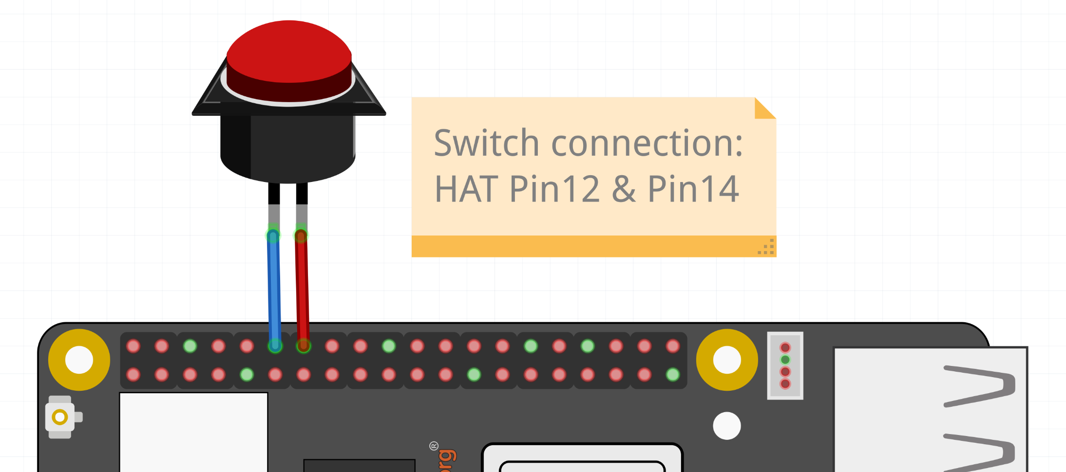
Similarly, a button is used for the GPIO read example, but you can also just connect that pin to 3.3V or GND with a wire to simulate a button press.
Todo
Add fritzing diagram and chapter on Pin Binding here
GPIO Write#
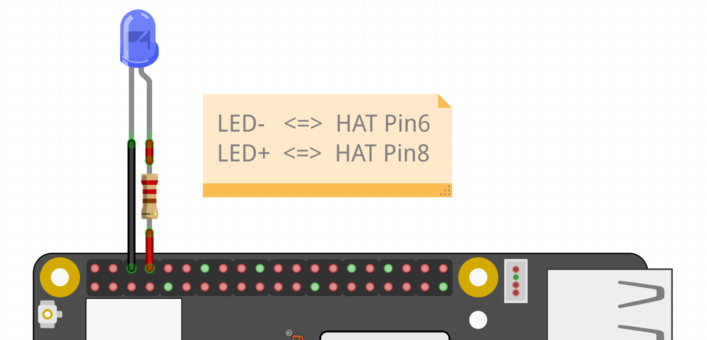
Fig. 115 LED connected to HAT Pin8 (GPIO14)#
At it’s most basic, we can set a GPIO using the gpioset command.
To set HAT Pin 8 (GPIO14) to ON:
gpioset $(gpiofind GPIO14)=1
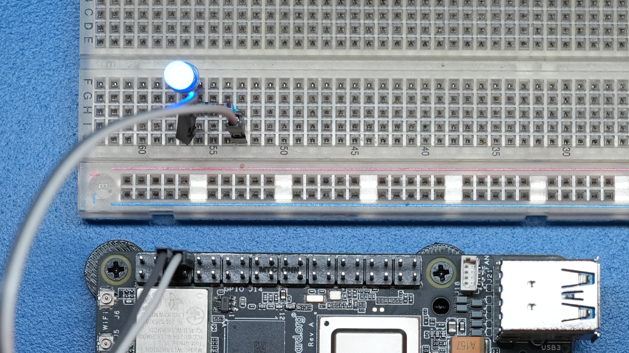
Fig. 116 GPIO ON state#
To set HAT Pin 8 (GPIO14) to OFF:
gpioset $(gpiofind GPIO14)=0
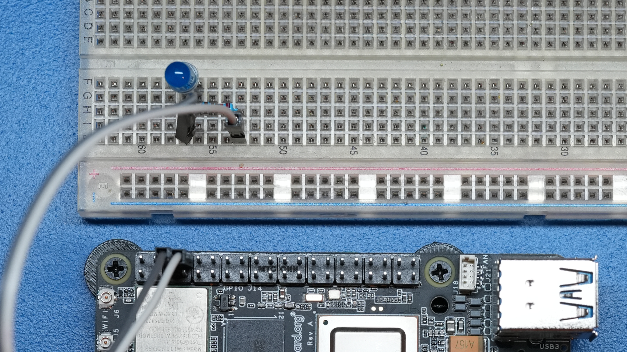
Fig. 117 GPIO OFF state#
Blink an LED#
Let’s create a script called blinky.sh,
Create the file,
touch blinky.sh
Open the file using
nanoeditor,
nano blinky.sh
Copy paste the code below to
blinky.shfile,
#!/bin/bash

while :
do
      gpioset $(gpiofind GPIO14)=1
      sleep 1
      gpioset $(gpiofind GPIO14)=0
      sleep 1
done
Close the editor by pressing
Ctrl + Ofollowed byEnterto save the file and then press toCtrl + XexitNow execute the
blinky.shscript by typing:
bash blinky.sh
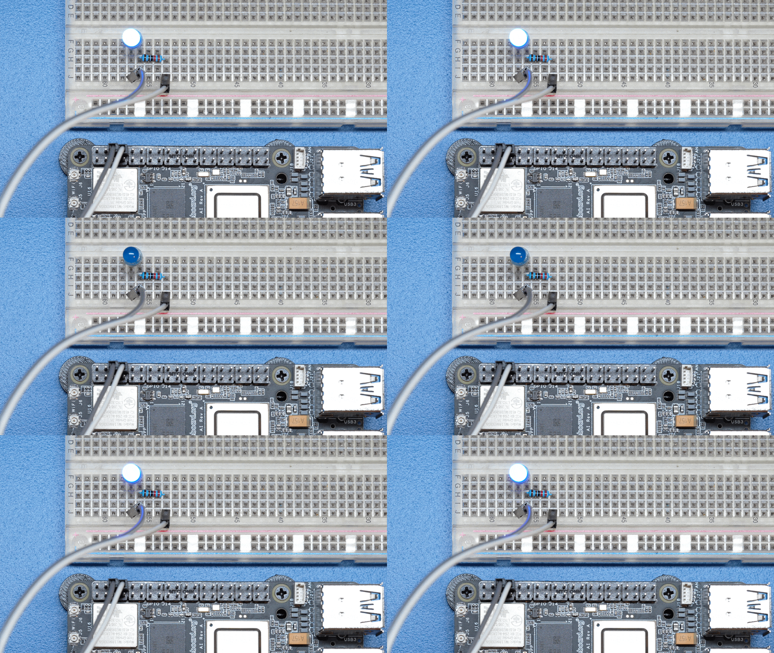
Fig. 118 LED blinking#
You can exit the
blinky.shprogrm by pressingCTRL + Con your keyboard.
Understanding the code#
#!/bin/bash

while :
do
   gpioset $(gpiofind GPIO14)=1 ①
   sleep 1 ②
   gpioset $(gpiofind GPIO14)=0 ③
   sleep 1 ④
done
The script is an infinite while loop in which we do the following:
① set the HAT Pin 8 (GPIO14) as 1 (HIGH)
② Wait 1 Second
③ set the HAT Pin 8 (GPIO14) as 0 (LOW)
④ Wait 1 Second
Combining the Two#
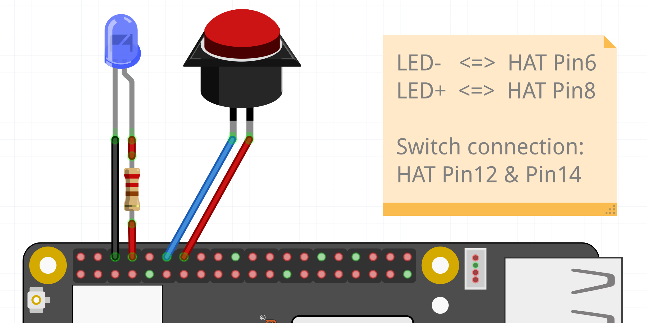
Fig. 120 Button connected to HAT Pin12 (GPIO18) & LED connected to HAT Pin8 (GPIO14)#
Now, logically, let’s make an LED match the state of the button.
Let’s create a script called blinkyButton.sh:
Create the file,
touch blinkyButton.sh
Open the file using
nanoeditor,
nano blinkyButton.sh
Copy paste the code below to
blinkyButton.shfile,
#!/bin/bash

while :
do
   if (( $(gpioget --bias=pull-up $(gpiofind GPIO18)) == 0))
   then
      gpioset $(gpiofind GPIO14)=1
   else
      gpioset $(gpiofind GPIO14)=0
   fi
done
Close the editor by pressing
Ctrl + Ofollowed byEnterto save the file and then press toCtrl + XexitNow execute the
blinkyButton.shscript by typing:
bash blinkyButton.sh
This means when we see HAT Pin 12 (GPIO18) go LOW, we know the button is pressed, so we set HAT Pin 8 (GPIO14) (our LED) to ON, otherwise, we turn it OFF.
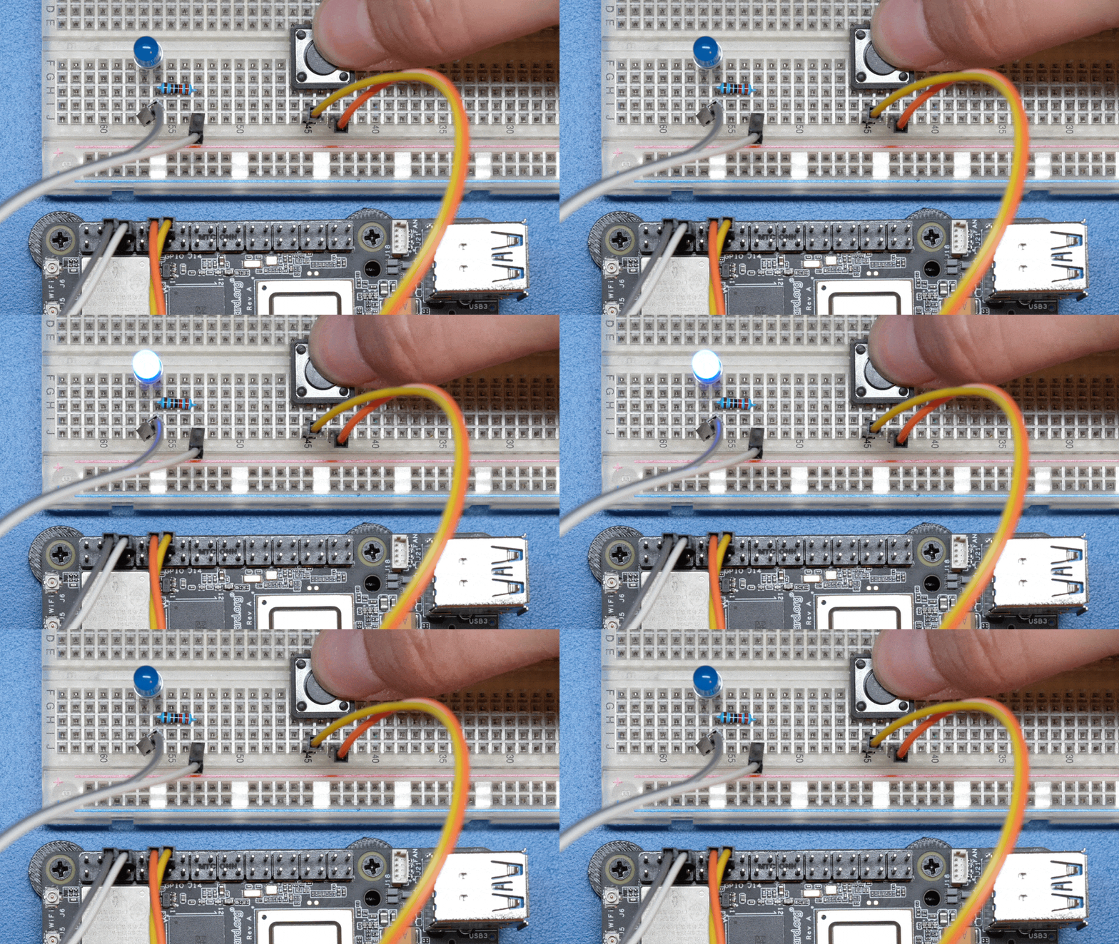
Fig. 121 LED is ON when button is pressed#
You can exit the
blinkyButton.shprogram by pressingCtrl + Con your keyboard.
Understanding Internal Pull Resistors#
Pull-up and pull-down resistors are used in digital circuits to ensure that inputs to logic settle at expected levels.
Internal pull-up resistorsconnects the pin to a high voltage level (e.g., 3.3V) to ensure the pin input reads as a logic high (1) when no active device is pulling it low.Internal pull-down resistorsconnects the pin to ground (GND) to ensure the input reads as a logic low (0) when no active device is pulling it high.
These resistors prevent floating inputs and undefined states.
By default, all GPIOs on the HAT Header are configured as Inputs with Pull-up Resistors Enabled.
This is important for something like a button, as without it, once a button is released, it goes in an “undefined” state!
To configure Pull-ups on a per-pin basis, we can use pass the following arguments within gpioget or gpioset:
-B, --bias=[as-is|disable|pull-down|pull-up] (defaults to 'as-is')
- The “Bias” argument has the following options:
as-is - This leaves the bias as-is… quite self explanatory
disable - This state is also known as High-Z (high impedance) where the Pin is left Floating without any bias resistor
pull-down - In this state, the pin is pulled DOWN by the internal 50KΩ resistor
pull-up - In this state, the pin is pulled UP by the internal 50KΩ resistor
For example, a command to read an input with the Bias intentionally disabled would look like this:
gpioget --bias=disable $(gpiofind GPIO14)
Pull resistors are a foundational block of digital circuits and understanding when to (and not to) use them is important.
This article from SparkFun Electronics is a good basic primer - Link
Troubleshooting#
My script won’t run!
Make sure you gave the script execute permissions first and that you’re executing it with a ./ before
To make it executable:
chmod +X scriptName.sh
To run it:
./scriptName.sh
Bonus - Turn all GPIOs ON/OFF#
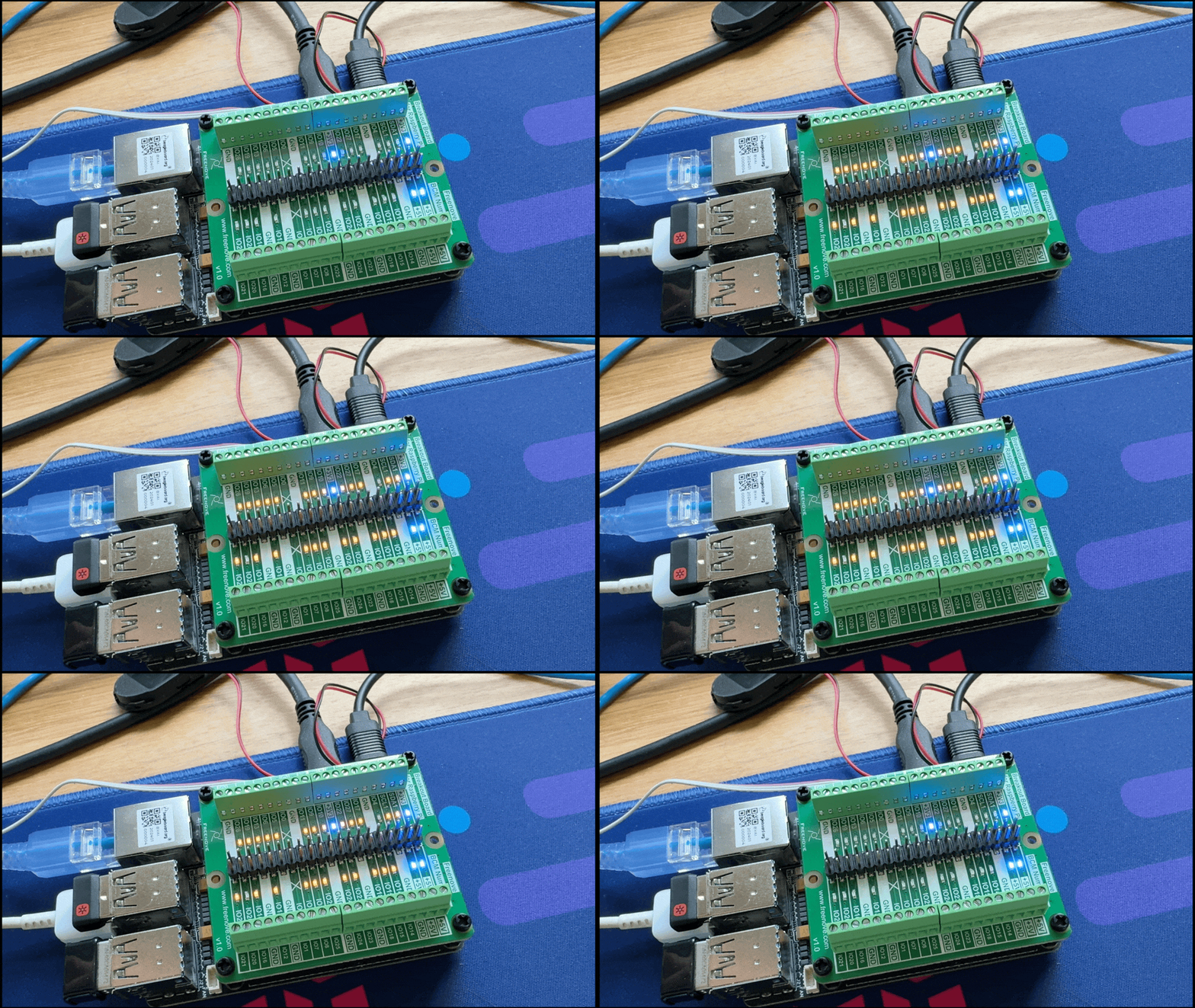
Fig. 122 All HAT GPIO toggle#
Copy and paste this with the button on the right to turn all pins ON.
gpioset $(gpiofind GPIO14)=1 ;\ gpioset $(gpiofind GPIO15)=1 ;\ gpioset $(gpiofind GPIO17)=1 ;\ gpioset $(gpiofind GPIO18)=1 ;\ gpioset $(gpiofind GPIO27)=1 ;\ gpioset $(gpiofind GPIO22)=1 ;\ gpioset $(gpiofind GPIO23)=1 ;\ gpioset $(gpiofind GPIO24)=1 ;\ gpioset $(gpiofind GPIO10)=1 ;\ gpioset $(gpiofind GPIO9)=1 ;\ gpioset $(gpiofind GPIO25)=1 ;\ gpioset $(gpiofind GPIO11)=1 ;\ gpioset $(gpiofind GPIO8)=1 ;\ gpioset $(gpiofind GPIO7)=1 ;\ gpioset $(gpiofind GPIO1)=1 ;\ gpioset $(gpiofind GPIO6)=1 ;\ gpioset $(gpiofind GPIO12)=1 ;\ gpioset $(gpiofind GPIO13)=1 ;\ gpioset $(gpiofind GPIO19)=1 ;\ gpioset $(gpiofind GPIO16)=1 ;\ gpioset $(gpiofind GPIO26)=1 ;\ gpioset $(gpiofind GPIO21)=1
Similarly, copy and paste this to turn all pins OFF.
gpioset $(gpiofind GPIO14)=0 ;\ gpioset $(gpiofind GPIO15)=0 ;\ gpioset $(gpiofind GPIO17)=0 ;\ gpioset $(gpiofind GPIO18)=0 ;\ gpioset $(gpiofind GPIO27)=0 ;\ gpioset $(gpiofind GPIO22)=0 ;\ gpioset $(gpiofind GPIO23)=0 ;\ gpioset $(gpiofind GPIO24)=0 ;\ gpioset $(gpiofind GPIO10)=0 ;\ gpioset $(gpiofind GPIO9)=0 ;\ gpioset $(gpiofind GPIO25)=0 ;\ gpioset $(gpiofind GPIO11)=0 ;\ gpioset $(gpiofind GPIO8)=0 ;\ gpioset $(gpiofind GPIO7)=0 ;\ gpioset $(gpiofind GPIO1)=0 ;\ gpioset $(gpiofind GPIO6)=0 ;\ gpioset $(gpiofind GPIO12)=0 ;\ gpioset $(gpiofind GPIO13)=0 ;\ gpioset $(gpiofind GPIO19)=0 ;\ gpioset $(gpiofind GPIO16)=0 ;\ gpioset $(gpiofind GPIO26)=0 ;\ gpioset $(gpiofind GPIO21)=0
